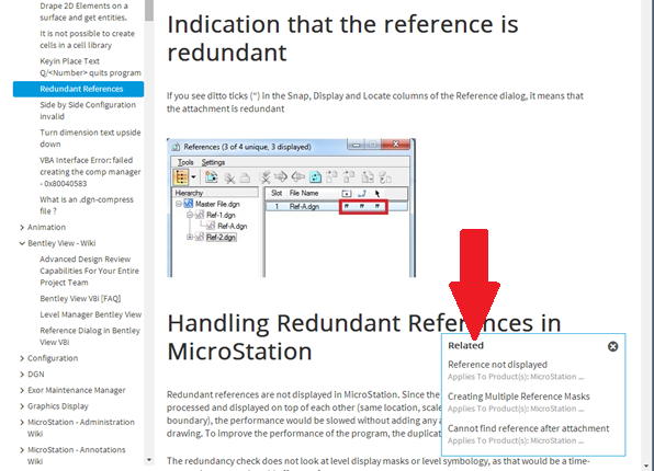
I’ve been picking away at the whole issue of where to model in 3D space for a long time. One of the sources of confusion is the use of ambiguous names or descriptions for some of the key concepts.
The threads we’re about to follow will hopefully clarify things.
Several settings and concepts interact or are important to understand:
- Units of Resolution
- Design File Centre
- Solids Working Area
- Global Origin
The waters can be muddied by comments such as “Solids Working Area should be set relative to the largest element you expect, are you modelling a watch or an airport?” which identify the existence of questions but don’t really give guidance on actual settings. I hope to provide some guidelines if not firm answers.
The Context
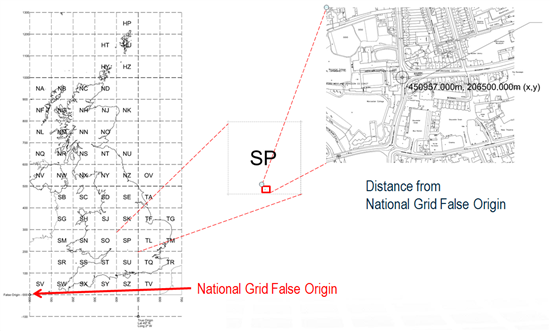
The UK context is that the furthest point on land is about 1300km from the National Grid Origin down in the Western Approaches.
2D? No problem, reference in an OS DXF file and you can draw away happily, 3D is more complex as I know some of you have already found.
You would think after working successfully in 2D MicroStation at real-world coordinates, and given a humungous Design Cube, modelling in real world locations in the UK, would be trivial.
Not so.
In ABD’s UORs the numbers get very big for coordinates where in Oxford, shown below, let alone in the Shetlands.
![]()
Units of Resolution
This is very basic but worth a review.
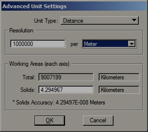
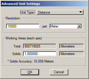
The precision of a DGN file is set by the Units of Resolution per Unit of Distance. In a 3D file this setting defines the extent of the Design Cube.
These are the current metric defaults for MicroStation. This default resolution for MicroStation was chosen as it is a more general purpose tool used across a range of disciplines, land use data for instance can obviously extend over large distances:
![]() =
= ![]()
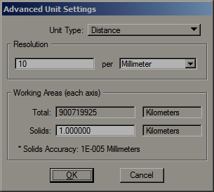
And for AECOsim Building Designer:
![]() =
= ![]()
The higher resolution set as default in the AECOsim Building Designer datasets is appropriate for the higher level of accuracy and smaller distances involved with individual buildings or smaller campuses.
Recommendation 1
Always use the same resolution across a project.
When working with a mix of MicroStation and AECOsim Building Designer it would generally be a good idea to set MicroStation’s seed files to match AECOsim, i.e 1000/mm. This is removes one opportunity for uncertainty or confusion and omits the scaling calculations that are executed when referencing files whose resolutions differ.
Exceptions will be managed by the applications but let’s keep things simple where we can!
Note: This is an administrative activity applied only to empty seed files! Change the Resolution and existing elements in a file will be resized so no one in your teams should change these settings.
The resolution can be varied if necessary for a particular situation.
Recommended limits are:
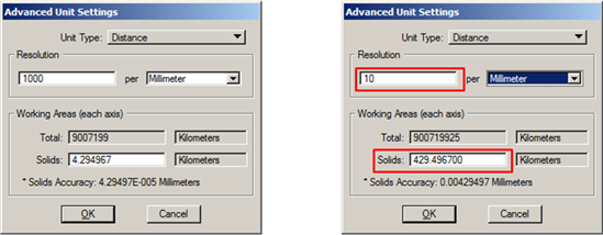
- Minimum: 1000/m [= 1/mm] for large scale infrastructure projects or similar.
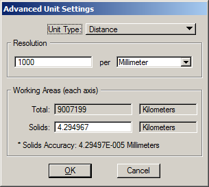
- Maximum: 1000000/m [=1000/mm] for buildings.
Set the resolution too high and you run into the accuracy issues that computers have with big numbers.
Set the resolution too low and you start missing detail in modelling and drawings.
Tip: Use the “SHOW UORS” key-in to see the numbers involved in your own models. Note the Message Center only displays the first four of 16 decimal places.
And while we are here, for the avoidance of doubt, note that other accuracy settings such as Working Units > Accuracy; Working Units > Angle Readout:
![]()
coordinate readout, decimal places on dimensions, etc., are only display settings. Sometimes people don’t understand that point and become concerned that they are reducing the accuracy of their models by changing them.
Design Cube
Using the AECOsim default resolution of 1000/mm gives us a Design Cube 9007199km along each edge. That’s about 2.5 times the distance to the moon.
So can’t I use all that space?
Not reliably! The further away from the Design Cube Centre you get the bigger the numbers are…
Floating point operations are dealing with numbers like this:
4387625962.1234567890123456
Note the 16 DP!
The limiting factors are those of floating point arithmetic. Double precision floating-point limitations apply to all modelling operations.
Many floating point calculations are carried out and each time a rounding off occurs (up to 16 places to the right of the decimal point). These roundings can accumulate to the point where positional errors can occur, potentially reducing accuracy or compromising operations.
The further elements are away from the Design Cube Centre the more effect rounding and floating point calculation limitations may have!
For standard brep solids, i.e. Bentley’s SmartSolids and Feature Solids, these roundings should not be an issue, but when other tools and features are involved problems can arise.
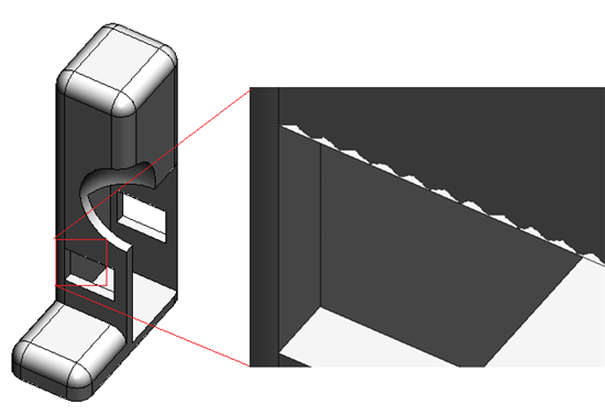
Simple tests appear to work just fine, I built a trivial model in the Shetlands, ran a series of Boolean operations, pushed and pulled faces, apparently no problem. However put a real building in the Shetlands and at some point things will go awry simply because of this arithmetic.
I did encounter an issue with graphics resolution in this model, note the white flecks were visible along some edges, zooming right in reveals them. This is not directly due to the distance from Design File Origin, see Zig-Zag Edges in Shaded Views for more details.
![]()
Recommendation 2
Always work ‘near’ the Design File Centre in AECOsim Building Designer.
…to avoid cumulative rounding errors. Working within the Solids Working Area set by the dataset seed files is the easiest way to meet this recommendation.
Solids Working Area
- The Design File Centre is a fixed point at the ‘0,0,0 UORs’ point of the Design Cube.
- Parasolid operations must occur near the Design File Centre.
- The centre of the Solids Working Area is coincident with the Design File Centre.
- The Solids Working Area does not move.
The centre of the Solids Working Area is coincident with the Design File Centre. The Design File Centre is a fixed point at the ‘0,0,0 UORs’ point of the Design Cube.
Parasolid is the engine that powers MicroStation and ABD’s 3D features. The SWA is simply a scale factor used when interacting with the Parasolid geometric modelling kernel’s design cube governing the resolution that Parasolid is operating with. (http://www.plm.automation.siemens.com/en_us/products/open/parasolid/index.shtml)
Operations involving 3D solids, from the simplest Boolean addition of two solids to the many operations involved in generating DEM or Dynamic/Building Views from a complex building, must take place within the Solids Working Area (SWA) so it is best to model within the SWA.
However, for any solid elements modelled beyond the SWA, MicroStation and ABD behind the scenes mathematically translate and scale them to a location near the centre of the SWA, store that transformation, perform the required operations, then transform the modified elements back to their original position and size. This is known as the floating SWA approach.
At this point I can hear the ghost of my maths teacher saying “I told you transformations were important!”
Default Solids Working Areas
MicroStation and AECOsim Building Designer have different default SWA’s.
In MicroStation the default SWA is 1km in extent.
In AECOsim Building Designer the default SWA is 4.29km. This was based on the v7 design cube for legacy reasons. The larger SWA also has benefits for the performance of DEM drawing unification. AECOsim Building Designer has been tested and certified using the default 4.29km SWA so it is recommended to use this default whenever possible.
Recommendation 3
Use the default ABD resolution and SWA settings whenever possible.
Changing the SWA
The SWA can be changed in size from the defaults but this will change the level of accuracy available when modelling. It is possible that this could affect certain tools or operations in AECOsim Building Designer.
There are two cases when you may need to change the SWA:
Elements larger than the SWA
The less likely case, but it has come up in urban design projects.
Boolean operations will be successful on any element that does not exceed the SWA in extent, operations on larger elements may fail completely or produce unexpected results. For instance a 4.2km cube element will almost fill the AECOsim Building Designer SWA and can be modified, but if rotated will extend beyond the SWA, operations would then fail.
If you need to model complete elements larger than the default SWA in extent the SWA can be increased in project seed files.
However our recommendation would be to break the elements down to smaller units.
Recommendation 4
Break very large elements down to smaller units to fit within the Solids Working Area.
Site larger than SWA
Either break the model down into separate models that fit the SWA and reference them together or increase the SWA.
We recommend breaking the model down and using referencing but if the project really demands it the SWA can be changed.
How near is ‘near’ to the Design File Centre?
A rule of thumb for changing the SWA to suit a large site has been suggested as follows:
- Assuming you have a project with relatively evenly distributed elements…
- Make sure that Design File Centre is at the centre of the site.
- Take the 3d range-box of all the elements in the project, expand it by 25%.
- Set the SWA to the length of the diagonal of that range.
- Use the AECOsim Building Designer default resolution of a 1000/mm if your project fits in a box up to 10km along each edge. The maximum UOR being calculated will then be 5,000,000,000 in any dimension.
- If the project is larger than the 10km box, consider sub-division of the project, or if that is not possible reduce the whole project resolution to 100/mm
Notes:
If you change the resolution of a design file the Solids Working Area will be scaled in proportion. Watch out for this. The size of the SWA should be manually set in line with the guidance given here when creating project seed files.
![]()
AECOsim Building Designer will handle files containing different resolution settings but this will involve an extra layer of internal scaling calculations with potential for further cumulative rounding.
Health Warnings!
- Changing the SWA and resolution for a project is not to be taken lightly.
- Avoid if possible.
- It should only be done by CAD/BIM administrators.
- It must be applied consistently to a project and documented.
Recommendation 5
If any working unit related settings are changed use consistent settings for the whole project.
So to recap:
- The Solids Working Area is positioned at the Design File Centre and is the space within which all 3D operations must be carried out.
- The Solids Working Area does not move.
- Its extent should be as recommended by Bentley wherever possible.
- If necessary The SWA can be changed in size to meet project requirements.
- Approach any changes to the Solids Working Area with forethought!
Where to Model?
How near is ‘near’ to the Design File Centre?
A good guide is:
- Within 5km at 1000 UOR/mm
- That is within 5,000,000,000 UOR
The UOR is the critical factor.
The Actual Numbers
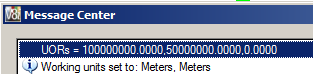
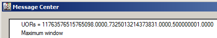
Take a look at the actual UORs at the edges of your model. Use the “SHOW UORS” key-in to see the numbers involved in your own models. Note the Message Center only displays the first four of 16 decimal places.
![]()
At Maximum Window the numbers are very large
![]()
Tip: Use Ctrl + Shift to activate AccuSnap for this command.
If any of those UOR values are more than 5,000,000,000 you are probably getting too far away.
Recommendation 6
If in doubt check the actual UOR coordinates of elements.
Values in excess of 5e9 UOR, that’s 5,000,000,000 in old money, are a warning.
Locating Projects in the Real World
Having established that we should model close to the Design File Centre we then have two methods to locate projects in the real world
- Relocation of the Global Origin
- geo-referencing via Global Coordinate Systems (GCS).
Global Origin
Sometimes confused with the Design File Centre, the Global Origin is a point that can be relabelled.
By default the Global Origin is coincident with the Design File Centre.
The Global Origin can be relabelled to meet various workflows.
This method is compatible with other applications that cannot store Geographic Coordinate Systems.
Example
Relabel the Global Origin to establish local setting out coordinates.
Use GO= tool > Monument Point and snap to the centre of the setting out point.
Important:
Always Save Settings after successfully relocating the GO, the new GO will not be auto-saved.
Use GO=$ to display the current GO offset from the Design Cube Centre
GO= tool > Center will reset to 0,0,0
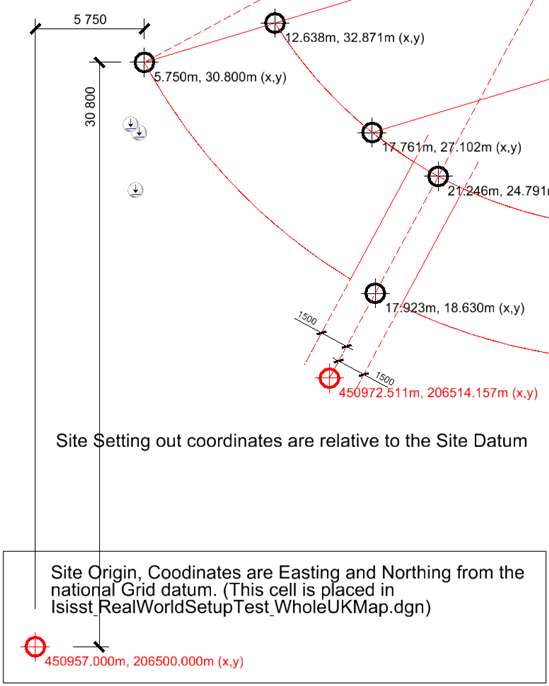
![]()
The red setting out points are in a reference file and relate to the UK National Grid origin, all of the black coordinates are relative to the Site Origin at lower left, a survey point South West of the site to ensure positive coordinates. By the way the coordinate markers here are cells containing text fields linked to the x,y coordinates of the marker’s centre. If the setting out point needed to be moved, just relabel the GO to the new point and update all text fields
Links
http://floating-point-gui.de/basic/
![]()
 =
= 
 =
=