Quantcast
Channel: Bentley Communities
Viewing all 4567 articles
Browse latest View live

Script error when installing STAAD in Windows 7 with non-English language.

$
0
0

You may encounter installer script error when installing STAAD in localized Windows, for example Norwegian. The error message is:

Error 1609. An error occurred while applying security settings. User is not a valid user or group.


Reason of this error is that installer can’t find a built-in group called Users, which actually exists but its name is translated. To work around this issue, please create additional group names as Users manually:

  1. Open Control Panel and go to Systems and Security (if you are in category view)
  2. Open Administrative Tools and launch Computer Management
  3. Find Local Users and Groups section in there and create new Users group in Groups folder

Note. If you are using Windows 7 Home Premium edition, Local Users and Groups section is not available in Computer Management. However user groups can be managed in command prompt nevertheless. Open command prompt and enter NET LOCALGROUP to list all groups available locally. If you don’t see Users in there, run the following command: NET LOCALGROUP Users /Add.

Once Users group is present locally, there should be no other obstacless to comple installation.

Applicable:
STAAD.Pro 20.07.09.31
Windows 7 Pro, Windows 7 Home Premium


Exploring Augmented Reality for Construction

$
0
0

Infrastructure is inherently 3-dimensional. Designers propose a 3D building concept, and ultimately builders create the 3D object that corresponds to the designer’s idea. Yet, the only design document that is legally approved for construction is the 2D drawing. Of course, 2D drawings are essential documents for construction, as they represent an efficient way of looking at and understanding the complex 3D model information. But the process forces designers, architects and engineers to take one dimension out of their 3D design.  Therefore, drafting consists of a complex set of tasks aimed at accurately representing 3D objects with 2D representations. The process is complex and must be done with great care, to ensure that when the builders read the 2D drawings, they will be in a position to build the 3D building exactly as it was designed.

Plans must be followed carefully. Unfortunately, construction workers cannot work with drawings in their hands – as they need their hands to do the construction work. They cannot constantly look at the drawings either. So drawings are often put on a table on the site, and workers frequently come to look at it, understand it, and to take measurements. In the process, errors may be made. A builder may take the wrong measurement. Or he may be looking at the wrong drawing. Or even just not looking at the drawing at all, basing his work on what he remembers from what he saw previously on the drawing. This happened when our family house was built: the builder had put the fireplace at the wrong depth with respect to the surface of the wall. When I showed him that the drawing clearly indicated it should be off the wall by 6 inches, he said: “You're right!... I had not seen it I guess...”  We really need to find better ways to look at drawings. Actually, we need to find better ways to look at the information conveyed by drawings.

Drawings contain lots of information about a building – one problem is that workers do not have the drawing constantly before their eyes. The fact that they sometimes have to manually measure distances on the drawings, make calculations, and hold figures in memory, may lead to error. They should carry the drawing with them, all the time. Even better: the drawing should be displayed on a tablet, which would display only the parts of the drawing that are appropriate for a given task (for instance: it would display just one of the 4 sections that appear on a given sheet, the one that matters to the worker at that specific time). But the drawing, on its own, is not the solution. A drawing is a representation of what should be built in the physical world - however that representation is very abstract... To fully understand it, one could lower the level of abstraction by displaying the drawing within a context.  Although drawings are 2D, they actually each represent a specific location in the 3D building. For instance, a section drawing represents a section of the wall at a specific (authored) location. Then why not display it right there? I mean display the drawing in the physical building, at the exact location it represents? Displaying the drawing in combination with the physical world may provide the context required to help understand the drawing better. Such a combined display could be achieved using Augmented Reality.

Our team has done quite some work in the Augmented Reality (AR) field. AR displays digital data in the context of the physical world. This helps interpreting the digital data (as it is then displayed in a context). It also helps interpreting the physical world, as it then comes with supplementary data. With augmented reality, the whole really is greater than the sum of its parts.  We have already explored the possibility of displaying 2D drawings in the context of the physical world, as represented by pre-recorded panoramic images (see our blog post), in a static augmentation experience.  We wanted to go one step further and let the augmentation be more dynamic.

In this project, we wanted to see what it would be like to build a building using a live AR system. How could we render (or present) the digital data in such a way that would be useful for the worker? Would the builder really benefit from it? What issues would need to be solved, to be in a position to make such a system operational?

So we developed a basic AR system for construction, that consists of:

  • a set of 3D video eyewear equipped with video cameras, 
  • an orientation sensor (for measuring the head orientation),
  • a set of 3D game controllers (for measuring the head position).

Our results are shown in the video below.

(Please visit the site to view this media)

We chose to develop our system using a head mounted display, as we started with the assumption that construction workers need their hands to do the work – so we needed to design a system that would keep their hands free. But other systems based for instance on ruggedized tablets could also be proposed, and would have other advantages.

You could probably see many flaws in the video, such as: bad tracking (which makes the drawings “float” above the floor), and no support of occlusion (which causes perception difficulties). In spite of those, the demo leads us to believe there is a future for AR in construction. If implemented properly and accepted by workers, such a system could probably help avoid mistakes, save accidents, and consequently speed up the construction process and lower costs. There are, however, many issues to resolve to make that possible. Those include:

  • Enhance the capacity to measure accurately the head position and orientation (that caused the "floating" effect of the model in the video);
  • Find ways to render the model in ways that support occlusion from physical objects (e.g. tools, studs in the way should occlude the model for it to look more “realistic”);
  • Make sure the system is safe to use – anything that is displayed before the user’s eyes has a potential for creating safety issues as it would prevent the user from seeing fully what is happening around him – and we all know there are many potential dangers on a building site;
  • Develop a system aimed at working in coordination with the worker, not at replacing him. Such coordination would likely lead to the highest outcome in terms of efficiency.

For sure, it appears that displaying 2D drawings in the context of the physical world helps a lot in conveying the design information. When displayed into a physical world context, drawings becomes easier to understand, and the physical world becomes easier to interpret.

One day, we may see all construction workers equipped with high end smart phones integrated into their clothes, with wireless display on their digital contact lenses, following detailed visual and verbal instructions from a construction app that is carefully coordinating the work of all the workers on the site.

This all seems far-fetched to you? Recently, I was talking with a user about the potential of augmented reality in the AEC industry. When I told him about that vision of AR for construction, he said: “Construction workers would never accept using such systems…”. Then he paused, and pursued, more slowly: “… well, back in the old days, we were building roads using levels and long wood studs to check our slopes. Now graders blades are GPS located and electronically controlled… and that is now widely accepted!

Someone famous once wrote: “The best way to predict the future is to invent it”…
Well, the future is ahead of us, and still largely unknown. Let’s invent it…

Updated patch sets now available for Water and Storm and Sewer products

$
0
0

The most current patch sets for the products listed below are now available to download from the "SELECT Released Products" section of SELECT Downloads webpage. Note that these patch sets must be installed after the full installation of the referenced product version (i.e., software download from "SELECT Released Products" section), and they cannot be used with any version other than that specified.

• Bentley WaterGEMS V8i - Cumulative Patch Set for build 08.11.04.50, posted 6/13/13
• Bentley WaterCAD V8i - Cumulative Patch Set for build 08.11.04.50, posted 6/13/13
• Bentley HAMMER V8i - Cumulative Patch Set for build 08.11.004.50, posted 6/13/13
• Bentley StormCAD V8i - Cumulative Patch Set for build 08.11.03.77, posted 6/13/13
• Bentley StormCAD V8i United Kingdom - Cumulative Patch Set for build 08.11.03.77, posted 6/13/13
• Bentley SewerGEMS V8i - Cumulative Patch Set for build 08.11.03.77, posted 6/13/13
• Bentley SewerCAD V8i - Cumulative Patch Set for build 08.11.03.77, posted 6/13/13
• Bentley CivilStorm V8i - Cumulative Patch Set for build 08.11.03.77, posted 6/13/13

There is a slight change to the process of downloading our patch sets. In the search screen, instead of choosing “Enhancements and Updates”, leave the Download Category as “SELECT Released Products”. Make sure the check box is checked for showing dependencies. In the search result, the patch will then show as a dependency of the main product. Note that the patch sets for WaterGEMS and SewerGEMS will be available to download from the "Enhancements and Updates" section as before.

Other items of note:

• All patch sets are cumulative; that is, they contain all available updates for the specific product and version up to the time of posting. You need only install the latest patch set to become current. 
• The software product must be closed prior to installing the update.
• Patch sets are refreshed on SELECTservices Downloads on a monthly basis.
• For further assistance with software updates and patches, please contact technical support at http://www.bentley.com/serviceticketmanager.

Note that these patch sets must only be installed on a machine where you have the specific product version listed above already installed. They are not compatible with any other version. To check what version you have installed, open the product, go to Help > About. The build number will be in the lower left corner of the dialog in brackets.

Learning Point Cloud Processing and Scalable Terrain Model with Bentley Descartes V8i (SELECTseries 4)

$
0
0

Hi,

got the inquiry few times by email so I thought it was worthwhile to mention we have a great course available to learn the latest Point Cloud processing capabilities as well as Descartes' Scalable Terrain Model.

This training, named Bentley Descartes for 3D Modeling,  was created by Inga Morozoff and is accessible on Bentley LEARN server.  

Happy Learning !

Ben

Show near and far points at bend

$
0
0

Hi,

I changed the near and far point names, but they don't show up on the drawing (only in input grid).

Can you guide me how to make them appear?

Thanks

Using the User/Group Management Dialog To Search Folders and Projects for a Group

$
0
0
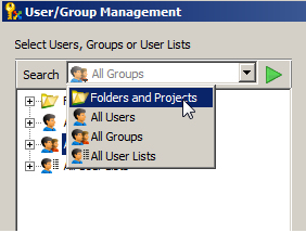
  1. Open the User / Group Management dialog in ProjectWise Explorer. (Tools > User Management) 
  2. Do one of the following: 
    Select the Folders and Projects node.
    or
    Click the menu inside the Search field and select Folders and Projects.
     
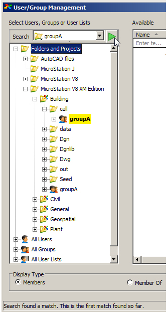
  3. In the Search field, enter the name of a group to search for.
  4. Click Start Search. 
    If a match is found, it is highlighted, and the status bar reads, "Search found a match. This is the first match found so far." If there are no matches for the entered text, the status bar reads, "No matches found."
    You can enter the full name of the group you are searching for, or you can enter any part of the name. For example, if the group you are searching for is named "groupA", then any of the following entries would produce a match:
    • groupA
    • groupa
    • GRO
    • upa
    • o
    Assuming a match is found, you can select the highlighted group to see its members, or to see which user lists it belongs to. You can also expand the group to see which users belong to it, and you can select any of the users in the highlighted group, to see which other groups and user lists the selected user belongs to.
  5. To see if the group is assigned to any other folders or projects further down in the folder list, click Start Search again. If another match is found, it is highlighted and the status bar now reads, "Search found another match. Total of 2 matches found so far."
  6. Continue searching the Folders and Projects node by clicking Start Search until you find the item you are looking for.
Note: A search will look for any name in the selected node that matches the entered text, so when searching the Folders and Projects node, your search might find folders, projects, groups, users, or user lists. 
Note: When searching the Folders and Projects node, the search will only search the selected folder or project in that node. So if you want to search the entire datasource, select the Folders and Projects node. If you want to search just a particular folder or project, expand the Folders and Projects node and navigate to and select the specific folder or project to search.
Note: In the Folders and Projects node, you only see folders and projects to which the user you are logged in as has access. So if you are searching for a group that is assigned to a folder to which you do not have access, you will not see that folder, and therefore you will not find that group. In that case, it may be better for you to search the All Groups node, as that node will show you all the groups in the datasource, whether you are a member of it, an owner of it, or neither.

eSeminar Bentley Map op 25 juni

Upgrading Revit? Read this First!

$
0
0

ProjectWise users that integrate ProjectWise V8i with Revit 2013 need to be aware of a couple of Revit related issues that have been reported to TSG.

Installing Revit 2013 Service pack 3

Revit 2013 Service pack introduces a slight format change that ProjectWise reports to the user. Once a Revit 2013 central file is synchronized
it won’t open from ProjectWise. The user gets the following error message:

(Error Dialog: The *.rvt was saved in a later version of Revit and cannot be opened in this version.)

The file can be opened from the local drive; so if you get this error message you will need to do the following:

  • There is no way to downgrade Revit. You will need to uninstall Revit 2013 SP3 and reinstall Revit 2013 SP2.
  • Send the bad file to a folder outside of ProjectWise.
  • Delete the *.rvt file and the corresponding *.dat files from ProjectWise.
  • Then using Revit 2013 SP2 recreate the central file in ProjectWise from the file sent to folder.

You will need to make sure that nobody with Revit 2013 SP3 opens files from ProjectWise until the issue is
resolved and Revit 2013 SP3 is supported. Once we have a fix for this issue we will post a reply to this blog
article.

Installing Revit 2014 with ProjectWise Explorer

If you install Revit 2014 one of the prerequisites is .NET 4.5.  ProjectWise 08.11.11.559 is tested with .NET
4.0. The installed .NET 4.5 is breaking integration in ProjectWise integrated Revit 2013 when elements are borrowed.

If you encounter this issue you can uninstall .NET 4.5 and restore .NET 4.0 to restore ProjectWise Integration with Revit 2013. Once we have a fix for this
issue we will post a reply to this blog article.

Application Integration Table

There is a ProjectWise V8i Application Integration Compatibility Table on BE Communities in the Content Management section:

http://communities.bentley.com/products/projectwise/content_management/m/mediagallery/177368/download.aspx

Any time you are working with an integrated application you should work with compatible versions. It is a good habit to check this table
before upgrading integrated applications.


Creating dropdown list to assign a value to a DEVICE_TYPE_CODE property based on a database query

$
0
0

Add EXTERNAL_DATSOURCE_DEFINITION_MAPPING and ExtendType custom attributes to DEVICE_TYPE_CODE property

Enter ShowPickListviewDataBase in ExtendType attribute's name field

Description of EXTERNAL_DATSOURCE_DEFINITION_MAPPING custom attribute.

Data connection string:

Provider=SQLOLEDB;Data Source=Your_Server_Name;Initial Catalog= Your_Database_Name;User Id=Your_Username;Password=Your_Password;

Sql Select statement:

SQL query to create the list

Property Mapping:

To map database fields with the EC Properties


Right click on property mapping and select “Add element”


ECProperty name:

The name of the EC property

Table Field name:

The name of the field in the database table


Below is example of custom attribute added to property. Screenshot and XML text:


<ECProperty propertyName="DEVICE_TYPE_CODE" typeName="string" description="code uses to describe the type of component." displayLabel="Device Type Code">            <ECCustomAttributes>                    <EXTERNAL_DATSOURCE_DEFINITION_MAPPING xmlns="pid.01.03">                    <DATA_CONNECTION_STRING>Provider=SQLOLEDB;Data Source=SSQL2008;Initial Catalog=myDataBase;User Id=sa;Password=q1w2e3;</DATA_CONNECTION_STRING>                    <FILENAME xmlns:xsi="http://www.w3.org/2001/XMLSchema-instance" xsi:nil="true" />                    <PATH_LOCATION xmlns:xsi="http://www.w3.org/2001/XMLSchema-instance" xsi:nil="true" />                    <SQL_SELECT>SELECT DISTINCT * FROM LIST</SQL_SELECT>                    <PROPERTY_MAPPING>                        <UPDATE_DEFINITION_STRUCTURE>                            <TABLE_FIELDNAME>LIST</TABLE_FIELDNAME>                            <ECPROPERTY>DEVICE_TYPE_CODE</ECPROPERTY>                        </UPDATE_DEFINITION_STRUCTURE>                    </PROPERTY_MAPPING>                </EXTERNAL_DATSOURCE_DEFINITION_MAPPING>                <ExtendType xmlns="EditorCustomAttributes.01.00">                    <Name>ShowPickListviewDataBase</Name>                </ExtendType>            </ECCustomAttributes>        </ECProperty>    </ECClass>

As a result drop down list should be shown in Placement Dialog 


eSeminar ontsluiten van GIS data

$
0
0

Hopelijk komt Bentley met meerdere eSeminar zoals gisteren gegeven door Marc Rietman.

Een uur uitleg is ook helemaal goed, voor het stellen van vragen was ook nog ruimte.

Insider Skills - Heading into Week 2

$
0
0

Week 1 for ProStructures went well and considering this was the very first Insider Skills presentation, the attendance was very good.  We covered a couple of topics including:

  • How to bring your software together through ISM / ‘Structural Synchronizer’.
  • Bridging the ProStructures MicroStation and AutoCAD platforms.
  • A look at other forms of model exchange such as native element conversion; neutral file formats; NC files for plates and beamlines.

Each topic was covered and shown briefly so that a general idea of what they are and how they work could be presented and the feedback from this was positive. 

If you like, you can find a recording of the first Insider Skills session at the Bentley Structural page on YouTube or by clicking >>> here <<<.

We are now coming up on the second ProStructures presentation which will be covering a few quick tips and tricks about the Detail Center and Detail Style. Some of the topics may include:

  • Using descriptions for views and dimensioning
  • Using the ‘Cut’ option to show hatching
  • Using the ‘Anchor’ option for views
  • Saving templates for the ‘detail center’ filtering.
  • Modifying the ‘US Mark Number’ (.mkn) file. 

With this in mind I hope you will join us again next Friday, July 5th at 1 PM Eastern / 12 Noon Central / 11 AM Mountain / 10 AM Pacific by clicking here to join at the specified time.

Announcement: ProStructures Online Training Schedule

$
0
0

We are about to post the ProStructures classes for the second half of 2013.

On the Learn server you will be able to register to:

ProSteel for MicroStation:

Fundamentals (3, 4 or 5 days):

    • Modeling (from Monday to Wednesday)
    • Engineering General Arrangements (Thursday) - Mandatory to be registered to Modeling class (or to have followed Modeling class at an earlier date)
    • Fabrication Shop Drawings (Friday) - Mandatory to be registered to Modeling & General Arrangement classes (or to have followed Modeling & General Arrangement classes at an earlier date)

For Advanced Users (3 days - Tuesday to Thursday)


ProSteel for AutoCAD:

Fundamentals (3, 4 or 5 days):

    • Modeling (from Monday to Wednesday)
    • Engineering General Arrangements (Thursday) - Mandatory to be registered to Modeling class (or to have followed Modeling class at an earlier date)
    • Fabrication Shop Drawings (Friday) - Mandatory to be registered to Modeling & General Arrangement classes (or to have followed Modeling & General Arrangement classes at an earlier date)

For Advanced Users (3 days - Tuesday to Thursday) – Prerequisite to have ProSteel modeling knowledge. Enginnering and Fabrication classes a plus.


ProConcrete for MicroStation:

Fundamentals (2 days – Tuesday & Wednesday)Prerequisite to have ProSteel modeling knowledge. Enginnering and Fabrication classes a plus.


The classes are not posted yet but will be very shortly on our Learn Server. They will be available as follows (all classes go from 8am to 5pm, Eastern Times - North America):


August:

  • 05 to 09 : ProSteel Fundamentals for MicroStation*
  • 13 & 14 : ProConcrete Fundamentals for MicroStation*
  • 19 to 23 : ProSteel Fundamentals for AutoCAD

September:

  • 10 to 12 : ProSteel Advanced for MicroStation*
  • 17 & 18 : ProConcrete Fundamentals for MicroStation
  • 24 to 26 : ProSteel Advanced for AutoCAD*

October:

  • 07 to 11 : ProSteel Fundamentals for AutoCAD
  • 15 & 16 : ProConcrete Fundamentals for MicroStation

November:

  • 04 to 08 : ProSteel Fundamentals for MicroStation*
  • 12 & 13 : ProConcrete Fundamentals for MicroStation*
  • 25 to 27 : ProSteel Advanced for AutoCAD* (because of American Thanksgiving days have been moved from Monday to Wednesday)

December:

  • 09 to 13 : ProSteel Fundamentals for AutoCAD
  • 17 to 19 : ProSteel Advanced for MicroStation*


* : classes that I should be delivering

Tip No.6: T.O.S. Elevation difference for elements in plan views

$
0
0

When generating general layouts, one can have ProSteel automatically give us the elevation difference between the default elevation of the plan view and any elements that are above or below it. Here we will look at the settings needed for this to work.

It is important to understand that the calculation is made in reference to the elevation of the workframe view (magenta rectangle) used for that particular plan view.

All the controls in order to do this are in the DetailStyle.

We will look at the plan view of this little structure, which has a few internal beams above TOS, some below and some at same TOS as Workframe.

The result will be a plan view like this:

Where only elements with TOS above or below TOS of plan view show their difference value (inside brackets) in reference to TOS of view.

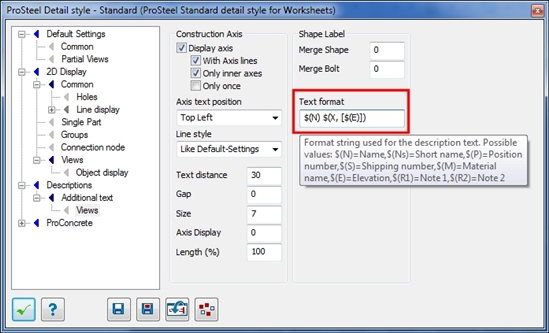
The way this was achieved was using a code inside the DetailStyle. In this case we used the $(N) for the name of the elements, followed by an “exception” rule, meaning that if the code inside this rule is empty (or equal to zero), the whole code inside this rule will be ignored. This makes it so that elements at “good” TOS elevation will not get a 0 (zero) value inside brackets. The exception rule  is the $(X, ????) where the ???? are replaced by whatever code you want to use. In this case we used the $(E) (which is the elevation of the element) inside brackets giving us a final code of:

$(N)$(X, [$(E)])

We could’ve used the following code $(N) $(X, [EL=$(E)]) to get a result like this W200x19.3 [EL=-40]

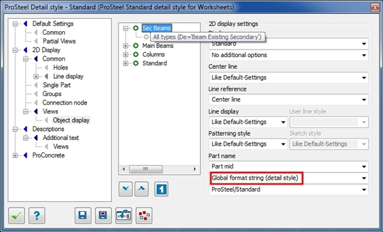
Now that the code is entered in the text format field, we also need to tell ProSteel to apply it to the elements we want to apply it (we do not want this for the columns in this view).

This is done by going back to the “Object display” page under  “2D Display > Views” and setting the Part name to be using the “Global Format String”


Warning for Transmittals users - hold off on upgrading to .NET 4.5

$
0
0

It has been determined that there is a change in how .NET framework 4.5 works that has caused problems in the functionality of Transmittals on client machines.  We are currently working with Microsoft to get to the root of the issue, however in the meantime we recommend also keeping .NET 4.5 off the Transmittals Server and Portal machines as well as the clients.  Any and all updates will be posted as comments to this blog.  As always, contact Bentley Technical Support if you have any questions.


Installing .NET framework 4.5 on your client machines will result in an error similar to the following when using Transmittals. 

Truncate Audit Trail for the first time in Off Hours

$
0
0

ProjectWise Admin module offers a setting for reducing the amount of records you keep in your Dms-audt  table (Audit Trail records). If you are truncating millions of rows in your dms-audt  for the first time, you should enable the checkbox for “Move truncated records into a secondary table” on Off Hours (perhaps on the weekend.) Otherwise, the ProjectWise Integration Server may not be able to function well and authenticate Users, etc. The setting is in the Properties of the Datasource > Audit Trail tab. The truncation process will start within the hour, and proceed until the specified number of records to be kept is reached. This could take days if this is truncating millions of records, and depending on the number of records specified to keep.  After the specified number of records to keep is reached, the Integration Server will be truncating only on an hourly basis, a much more modest number of records.

You can stop the ProjectWise Integration Server “Services”, and then uncheck the “Move truncated records into a secondary table”, then Restart the “Services” in you have to operate more efficiently before the truncation  process has completed.    

ProjectWise TSG can advise on more specific recommendations depending on what type of database you have, and if you have to truncate in a ProjectWise Integration Server Load-balanced configuration.


Scott Lofgren Student Design Competition award ceremony for the student at AGH University of Science and Technology in Krakow, Poland.

$
0
0

For the third time in five years a student from AGH, Krakow in Poland is a winner in our annual Student Design Competition, this time in the “Innovation in Rendering Using MicroStation” category.


The award ceremony took place on 7TH June at AGH in Krakow and it was attended by Vice-Rector Prof. Dr. Anna Siwik, Vice-dean of Faculty for Geology, Mining and Environmental Engineering Prof. Dr. Stanislaw Gruszczyński, Vice-Dean Prof. Dr. Beata Hejmanowska, Vice-Dean Dr. Tomasz Lipecki, Prof. Dr. Artur Krawczyk and many friends and family members of the winning student, Mateusz Ilba.


His winning project was titled the “Church in Trinidad Bay”  which was recently featured on a local TV Station program under the title: "AGH-UST Internationalstudents achievements")

In his speech, the representative of Bentley Systems, Poland- Miroslaw Pawelec, stressed the importance of education for the future of engineering industry and the leading role that AGH University of Science and Technology plays in sustaining the
infrastructure profession.

Mateusz Ilba standing side by side with former winners from AGH, Tomasz Majkusiak and Micha Marek “2012- Design of Nowy Kleparz Interchange” and Dominik Galica and Maciej Wloderczyk“2008- Photorealistic Visualization of Mine Workings and a Mechanical Coal Miner

Congratulaions to Mateusz on his excellent work, but also to Professor Dr. Artur Krawczyk and his team who manage to inspire students to achieve excellence in engineering education and also AGH University for creating an environment where such a work is encouraged and appreciated.


Opnames van eSeminar - Ontsluiten GIS data in Bentley Map - beschikbaar

$
0
0

De opname van het eSeminar van 25 juni 2013 over het ontsluiten van GIS data in Bentley Map is te bekijken op onderstaande link:

http://bentleyna.adobeconnect.com/p7plc9h8puj/

De opname is het in het Nederlands en duurt 59 minuten.

Onderwerpen die aan de orde zijn komen oa.:

  • Importeren Shape (Punt, lijnen, vlakken)
  • Importeren XY bestand
  • Importeren Oracle Spatial
  • Importeren WFS
  • Exporteren Shape
  • Exporteren Gml
  • Connecten naar WFS en Oracle.
  • Gebruik van FME plugin
  • Gebruik van Key-in's

Als er nog vragen zijn neem dan gerust contact op via Marc.Rietman@Bentley.com


Ontsluiten Obliek foto's in Bentley Geo Web Publisher

$
0
0

Slagboom en Peeters luchtfotografie levert obliek foto’s. http://www.slagboomenpeeters.com/obliek.html

Deze foto’s worden via een online viewer ter beschikking gesteld.

De foto’s zijn te benaderen via een URL die opgebouwd is uit  een applicatiecode en een XY coordinaat.

De applicatie wordt door Slageboom en Peters verstrekt. X en Y dienen uit een databron gehaald te worden.


In bigevoegd document wordt uitgelegd hoe deze foto’s vanuit Bentley Geo Web Publisher ontsloten kunnen worden.

Tevens is een acces database toegevoegd met een voorbeeld query.


Bij vragen neem contact op via Marc.Rietman@Bentley.com


Bentley LEARN - freie Beispiele von der LEARN Konferenz

$
0
0

Mit Bentley LEARN lernen Sie auf Abruf

- und zwar immer mehr punktgenau das was Sie das Wissen wollen.

Einen Einblick in das Angebot finden Sie auf http://LEARN.BENTLEY.COM

Melden Sie sich als Gast an oder gleich mit Ihrem Bentley Login.


Schauen einfach mal um - zum Beispiel indem Sie eingeben.


Dort finden Sie unter Anderem einen "Lernpfad" frei verfügbarer Sessions von der BE LEARNing Konferenz


Alle mit FREE gekennzeichneten Inhalte können Sie nach Anmeldung kostenlos anschauen.
Wenn Sie noch keinen Account haben erhalten Sie einen nach wenigen Angaben unter

Fragen Sie nach - unsere Learn Coaches begleiten Sie - jetzt und wenn Sie in Zukunft den richtigen Lernpfad für sich und Ihre Organisation finden und weiterentwickeln.

Deutsche Inhalte gibt es schon jetzt - die LEARN-Seiten werden auch in Deutsch verfügbar sein.

ProjectWise DMSKRNL.cfg Database Encryption

$
0
0

At the bottom of the dmskrl.cfg file,  you may have noticed the following three lines.

DBUserName=saadmin (NOTE“saadamin” is the database user name and may be different for your system)

DBUsrPwdDecrypt=4

DBUserPassword=#KrYVjkjpjyQdFbDqjllJZdGWACFLOsI+umQ==


This section is for the database user account used by the ProjectWise Integration server to connect to the database. You can see the user account name (DBUserName = ) and you will need to know the
password.


Notice that the dbuser id is in plain text ( saadmin ) but the password is encrypted.


Two symptoms you may run into if the Integration server is having trouble with the DB password.


1. The option in ProjectWise Administrator will be grayed out (PW Administrator | datasource | properties | database users
tab) and you will not be able to change it.

     
    2. You will get a Last Error 56057 Cannot login to the datasource. Database authorization failure. This is when you try
    to login via ProjectWise Explorer or ProjectWise Administrator.


    To fix these you can change the value of the “DBUsrPwdDecrypt”  in the dmskrnl.cfg file to 0 which will allow you to reset the Database user account password to
    plain text. Save the file and rest the integration server. You can now see the password in plain text, until you restart the Integration service. After restarting the Integration service it goes back to encrypted. The steps to test/perform this reset are as follows:


    Log into the dmskrnl.cfg file and go to the end of the file


    Locate your datasource and find the line “DBUsrPwdDecrypt=4”


    Change this value to 0 and enter the correct DB password for that ID


    Save the file and restart the PW Integration server


    You should now be able to log back in. Note that you will need to know the correct password for that “saadmin” account.


    Now open up the dmskrnl file again and go to the bottom.


    Notice how the value has now changed back to a 4 and the password is encrypted?


    Viewing all 4567 articles
    Browse latest View live


    <script src="https://jsc.adskeeper.com/r/s/rssing.com.1596347.js" async> </script>