Quantcast
Channel: Bentley Communities
Viewing all 4567 articles
Browse latest View live

Mice in Space!

$
0
0

"It's Friday, it's five to five. . . It's Crackerjack!" ...but this week instead of a Crackerjack pencil, settings files for your 3DConnexion SpaceMouse!

Out of the box the 3DConnexion devices offer some fairly generic windows commands. Adding MicroStation commands to your individual user profile is well handled by the 3DConnexion GUI but wouldn't it be great if you had a good starter set of Bentley specific commands that could easily be distributed to anyone using a SpaceMouse?

This requires some delving into the 3DConnexion profiles, matching up the device button names and the codes that link to them, followed by carefully pasting in custom commands created with the 3DConnexion GUI.

How to do this will be the subject of a future technote, but in the meantime please try out these files for MicroStation and AECsim Building Designer: SpaceMouseSettings_v1.zip. Settings are currently included for  Navigator, SpaceMouse Pro and SpacePilot Pro devices.

Files for Bentley Navigator, Bentley View and PowerDraft (because you can work with 3D files in PowerDraft) will be added once tested.

Download and paste into C:\Program Files\3Dconnexion\3Dconnexion 3DxSoftware\3DxWare64\en_us\profiles\default (rename the existing microStation.scr to .bak if you want to go back to it).

Once the 3DConnexion services are restarted the new profiles will be available, as you switch focus to MicroStation or AECOsim the new settings will be activated. The settings for AECOsim Building Designer with the SpacePilot Pro are shown here:

In addition I’ve also included an extensive list of F-key combinations:

as this will allow you to make use of the easily customisable F-keys in MicroStation to add any other command without having to delve further into the button settings in the SpaceMouse driver. Just use your existing MicroStation/AECOsim F-keys or create new ones, then use the menu on each button to associate the F-key that you want to use.

3d Input Toolbox.

To help control the SpaceMouse movements there is a set of tools, how they work is described in MicroStation help > Getting Started > Fundamentals > Graphical Input > Graphical Input with a 3Dconnexion Device.

To lauch the toolbox either Ctrl +T to open the Toolboxes dialog, tick 3dInput, or key-in: VIEW NAVIGATION 3DINPUT TOOLBOX.

It's worth keeping this docked if you frequently use a SpaceMouse.


Insider Skills - Session 02

$
0
0


Even with the July 4th holiday in the USA yesterday, attendeance was good. A wonderful group of people turned out to check out some of the information provided in the latest Insider Skills session. This weeks session focused on 2D Detail Center related items and covered things like using the 'Anchor Point' & the use of 'Descriptions' in the 2D drawings as well as a few other topics. As a matter of fact, though three and sometimes four topics are presented, this was an unprecedented five topics which meant that each topic needed to be covered quickly in order to finish on time. The presentation went well however and many satisfied attendees responded with positive feedback. So thank-you all, you should know that your feedback is always appreciated, whether it is positive or otherwise.

For anyone who did not get to attend this session a new session for ProStructures is held on the first Friday of each month at 1PM Eastern. More information can be found here:  >>> Click Here <<<  Additionally if you are interested in AutoPIPE, RAM or STAAD.Pro, the same link provides information on how you can attend the Insider Skills sessions that apply to each of these.

 Let me end by saying, I hope to see you all at the next session and if anyone missed the first 'Insider Skills' session you can find it online here: >>> Click Here <<<

EDIT: July 10, 2013

The second session has just been posted and can be found here:>>> Click Here <<<


Windows 8 and .Net 3.5

$
0
0

With the redaction of Win XP and the partial withdrawel of Win 7 (still supported but not supplied on new computers anymore) you will likely have spotted that any new computers come with a pre-installation of Windows 8.  This new operating system - mostly designed to be used on touch screens - is essentially the same as Windows 7, but with some new graphical twists.

Windows 8 has not been short of controversy with the likes of the Start menu being removed (I understand that this has now been reintroduced with the latest Microsoft update for Windows 8) but one issue that is slightly more pressing was the removal of .Net 3.5.

Windows 8 is provided with .Net 4.5, but not 3.5. This is rather surprising as 4.5 is not a programatical update to 3.5 but contains different functions and doesn't carry all of 3.5 functionality.  To this end you may have difficulty installing software onto your new Windows 8 computer until you have updated it to include .Net framework 3.5.

The processes for applying .Net framwork 3.5 to Windows 8 can be found here

User Synchronization Service as an Intermediate Login Provider

$
0
0

What if we have an integration server in one office that is not on a domain and we have a contractor connecting to it from another office who has a caching\gateway server in their office.

The contractor wants to have his domain user accounts synch with PW.

In SS4 there is a new feature that allows you to install the user synch service on a server at another location and synch users.

If your ProjectWise Integration Server cannot access the local domain controller and authenticate Windows users, you can install ProjectWise User Synchronization Service on a local area network (LAN) to act as an intermediate login provider for ProjectWise users with Windows accounts. In support of this, a new setting has been added to the dmskrnl.cfg file, UserSyncService=, which lets you specify the computer on which ProjectWise User Synchronization Service is installed. See the SS4ru ProjectWise Implementation Guide Chapter Page 128 for more details about setting this up.

Here is the excerpt from the dmsknrl.cfg

Here is the excerpt from the dmsknrl.cfg
; If ProjectWise Integration Server is installed outside the local network,
; for example on a Cloud virtual machine, it cannot access the local domain
; controller and authenticate Windows users. In that case, User Synchronization
; Service can be installed on a local network (LAN) to provide delegated logins
; and allow synchronized Windows users to access ProjectWise Integration Server.
; To enable User Synchronization Service delegated logins, the UserSyncService
; option below must be set to the name of the local machine on which User
; Synchronization Service is installed. Also, the IP address of the User
; Synchronization Service machine must be added to the [Trusted Servers] list in this file.
;[db0]
;UserSyncService=<User Synchronization Service host name>

So in the dmskrnl.cfg on the integration server, at the top of the file in the Trusted Servers section

[Trusted Servers]
UserSync = 192.168.1.1

And at the bottom of the file where the datasources listings live you would add the line under each datasource that would synch users from another domain

[db0]
Description=MyPWDatasource
Type=Microsoft SQL Server
InterfaceType=ODBC
Name= MyPWDatasource
DBUserName=PWDBA
DBUsrPwdDecrypt=4
DBUserPassword=xxxxxxxxxx
UserSyncService=mysyncserver.bentley.com
 

I am told a "gotchya" to this setup is that the service uses Windows Challenge/Response (NTLM) as the authentication protocol which is turned off on most modern servers in favor of using Kerberos.  So some tweaking of the windows server might need to be done.

For more info on NTLM see http://msdn.microsoft.com/en-us/library/windows/desktop/aa378749(v=vs.85).aspx

Bentley Award Presentation at Curtin University, Western Australia

$
0
0

Bentley Award Presentation at Curtin University, Western Australia

On June 14th, 2013, Ivy Branson came for Bentley Award Presentation to students at Curtin University.  The award recipients were students of class Construction Technology 463, which was a Unit offered by Department of Civil Engineering as part of its four-year course of Bachelor Degree in Civil and Construction Engineering.  The Unit emphasised on the importance of design and construction aspects of specialised structures such as prestressed concrete bridges and multistorey buildings.  

Bentley software used by students included CON BOX, AECOsim, NAVIGATOR, and STAAD Pro.

The Unit was delivered by Dr Vanissorn (Sorn) Vimonsatit and assisted Nadim Abushawashi, a Teaching Assistant currently completing his PhD.

Prizes were given to top students based on their combined assignment marks.  Assignments required students to work in teams developing an analysis and design solution for a prestressed concrete bridge using CON BOX, 3D simulation of a multistorey building construction using NAVIGATOR, and 3D structural analysis and design of a multistorey using STAAD Pro.


Award Winners based on top combined assignment marks, (L-R) Christopher Winduss, Anthony Mclellan, Nicholas Brown and Nicholas Nielson.  Another student also received the award but not in the picture was Michael Ehlers.


 Ivy Branson presented an award to Anthony Mclellan.  Also in the picture were Nadim Abushawashi  (left) and Dr Vanissorn Vimonsatit (right).

Christopher Winduss received his award.  Both Anthony Mclellan and Christopher Winduss received the award for their work on the construction simulation of a multistorey building using NAVIGATOR.

Nicholas Brown and his award

Nicholas Nielson and his award. 

Nicholas Brown, Nicholas Nielson and Michael Ehlers (not in the picture) received the award for their top marks based on the use of CON BOX and STAAD Pro.


Students’ work on a multi-storey construction simulation by NAVIGATOR based on a model provided in AECOsim

3D Atrium model by STAAD Pro.  Students were able to create 3D model of their own, and import/export the model for BIM development with STAAD Pro.


Analysis and Design of Prestressed Concrete Bridge by CONBOX.  Students were able to provide the detailed design of tendon profile, maximum stresses and box-girder section of a multiple-span bridge. 

ProjectWise Quick Search

$
0
0
Hate going in to the forum and seeing all those search options. You will need a guide to use the regular forum search. The search however via the forum or the quick search is a powerful tool. 
this post will cover few tips on how to use the quick search and the different syntax's you can use to run a search.
First off, there are a three default searches that are listed under the magnify icon in the quick search field   click on the icon and it will bring three pre-defined settings: All Content, Full Text Search and Document and Folder Properties (this includes project name and descriptions but not project properties) (SC1) Under Settings you can even set the default search as well keep number of searches in history.
SC1
All Content: will search every thing such as attributes, Full Text  document and folder properties. 
Full Text Search: will search all text in a file.
Document and Folder Properties: will search Document and folder Properties
If you click on settings you can create your own custom searches and give them unique names.
Once you create it it will be listed in the drop down.
 
*Another cool little tip not many know is you can actually right click on the field after you typed your text to search and select either to search the entire datasource, current folder or Environment*

When running searches here are a few syntaxes you can use to get more of an accurate search.
If you know the whole phrase then type it in with double quotes (ie. "Gas Authorities")
If you know part of the phrase then type it in with wild cards (ie. *Gas*) it will return all entries with Gas in it. 
following Operands can be used in the quick search:

Operands

Comments

Notes

AND

Two separate expressions can be combined with AND in one field

While quick search supports the use of AND, you do not need to include "AND" between criteria items, because a blank space will always be interpreted as an AND operand.

OR

Two separate expressions can be combined with OR in one field


NOT

Can be used with all criteria; NOT *pump, NOT NULL, <> A?


Critical Issues in CONSPAN v12.01.00.57

$
0
0

Critical Issues in CONSPAN v12.01.00.57

A couple of critical design issues have recently been identified in CONSPAN v12.00.01.57. Users should review these two issues carefully and verify the impact on prestress girder designs. These issues are being fixed, and the fixes will be included in a new release which will be available on SELECT at the end of July. If you have any questions or need additional information regarding these issues, please contact technical support at 1-800-778-4277, option 6 then 7 for LEAP.


  1. Vertical Shear: When the option to use Simplified Shear procedure (LRFD article 5.8.3.4.3) is used, the design shear Vu was incorrectly using the shear corresponding to the maximum moment
    rather than the maximum shear. Since this could lead to potentially underestimating the shear reinforcement required, users should not use this option, and should use the other options available under Design Parameters / Moment and Shear Provisions tab, i.e. the Beta Theta Tables or the Beta Theta Equations method.
  2. Live load distribution factor for multi-stemmed beams: When using Lever Rule the distribution factors were computed incorrectly by considering the distance from the edge of curb to the center of exterior web rather than to the center of the beam. This issue only affected exterior beams, and could be critical if the exterior beam governed the design.

Award presentation at Eastern Technical High School: the Scott Lofgren Student Design Competition

$
0
0

On May 20th, yet another student from Eastern Technical High School (Baltimore, Maryland, USA) was presented with a prize in Bentley’s annual student design competition.

Francis Jacaban won the “Design a Retail Center” category for the High School/Technical School level.

Francis brought the title back to Eastern Technical High after a brief hiatus last year. Students from the school have won the High school/Technical school category 6 times in the last 8 years--including 2006-2008, 2010 and 2011, and again for 2013. (Randolph High School in New Jersey claimed the trophies for the category in 2009 and 2012.)

This year, the challenge for the category was to develop an efficient retail center that meets the needs of thousands of diverse shoppers per day; the shopping center must also permit good traffic flow, and provide easy access from multiple forms of transportation. 

Senior Francis Jacaban from Eastern Tech earned the first place prize and scholarship with his project, Union Station, Washington D.C. He proposed an alternate design for the station that incorporates easy train and metro access, with a retail center that provides convenient shopping for commuters and local residents. Francis’ project also includes green design for storm water management, using pervious pavement and grey water collection. 

Pictured from left to right are Mr. Peter Glaudemans (his teacher), Mr. and Mrs. De Las Penas (uncle & aunt), Mrs. Maria Jacaban (proud mother), Francis, Mr. Thomas Evans (Principal), and Dr. Laura Meier (Bentley’s Academic Program Director).

All of the submissions in the student design competition are evaluated by an independent jury, comprised of educational leaders and industry users of Bentley software. Winning projects are selected for their creativity, excellent application of design and engineering principles, and effective use of Bentley software.

To read the press release about all of the winners, including the 2013 Bentley Educator of the Year, click here.

More information about the 2013 winning projects and Educator of the Year can be found on our webpage here: www.bentley.com/studentdesignwinners.


gINT Training Makes Local News in Doha (Qatar)

$
0
0

A recent course on using gINT Professional held in Doha in the State of Qatar was featured in the local Baladiya News, and posted online.

The inset photo shows Johhny Martel, a Bentley consultant, demonstrating the reporting process for subsurface data in gINT to the students.

Did You Know? RAM Connection Shear Connections

$
0
0

Did You Know… RAM Connection has an extensive library of connection types built into the program? I frequently am asked, "Can RAM Connection do [     ]?" where the blank is filled in by a specific connection type.

This will be the first of two blogs providing an overview of connection types in RAM Connection. In today’s blog, I will cover shear connections. Moment connections and combined connections will be addressed in the next blog.

Most connection types in RAM Connection are available two ways:  Basic or Smart.  In the instance where a connection is only available as one type, I have noted it.  Otherwise, the connection is available as both types.

For a quick reference guide of connection types and their descriptions, download the attached PDF.

The following is a list of the majority of the shear connections available in RAM Connection.  This list was compiled for beam to column connections except where noted as a splice connection.  This is not an exhaustive list.  RAM Connection is customizable and it would be difficult to itemize every single connection available.

Shear Connections

1. Shear Plate

2. Through Plate (HSS) [Basic only]

3. End Plate Bolted

4. End Plate Welded

5. Double Angle All bolted

6. Double Angle All welded

7. Double Angle Welded to Support, Bolted to Beam

8. Double Angle Bolted to Support, Welded to Beam

9. Bent Plate Bolted (can also be welded) [Basic only]

10. Shear Tee All Bolted

11. Shear Tee All Welded

12. Shear Tee Bolted to Support, Welded to Beam

13. Shear Tee Welded to Support, Bolted to Beam

14. Stiffened Seated Angles

15. Stiffened Seated Plate

16. Stiffened Seated Tee Bolted [Smart only]

17. Stiffened Seated Tee Welded [Smart only]

18. Unstiffened Seated Bolted

19. Unstiffened Seated Welded

20. Column Splice Flange Plate Bolted [Basic only]

21. Column Splice Flange Plate Welded [Basic only]

22. Column Splice Shear Plate [Basic only]

23. Beam Splice Shear Plate

24. Beam Splice Double Angle [Smart only]


Update Labels of a Hydraulic Model using WaterObjects.NET

$
0
0
Update Labels of a Hydraulic Model using WaterObjects.NET

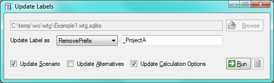
Update Labels main window


Introduction
Need to combine two models together and planning to use Submodel import/export feature? Everything will work perfectly fine as long as labels are different and if they are not, things will get overwritten where labels are same between the models. If in case there is a label like 'P-1' in both models and they need to be brought in separately, this tool, Update Labels, will help. The tool will allow to append, prepend, remove append or remove prepend a given text to ALL labels related to SubModel Import / Export . It will go to every nook and corner and update the labels.

Sometime there are situations with Scenarios, Alternatives and Calculation Options (SACO) were we do wants things to be overwritten. Considerting this in mind the tool offers options whether to overwrite the SACO.

The programming details covered herein are applicable to several of Bentley’s hydraulics and hydrology (H&H) applications including WaterGEMS, WaterCAD, HAMMER, SewerGEMS, SewerCAD, SewerGEMS Sanitary, CivilStorm, StormCAD, PondPack etc. In fact, the exact same lines of code can be used to create the tool that can work with most H&H applications. The tool will work with WaterGEMS, Storm Sewer STSWProducts SS3 such as SewerGEMS, SewerCAD, CivilStorm, StormCAD and PondPack.
How to Run the Tool
If you simply obtain the executable (.exe) file then make sure to place/copy this file in the right directory. For eaxample, for UpdateLabels.Water, the .exe needs to be placed in the %ProgramFiles%\Bentley\WaterGEMS\ directory or in corresponding STSW installed directory. Once the exe file is in the right location, run it and a window as shown in the figure above will show up.

In the Update Labels tool, click on Browse button and select the model database file. Select the Update Label as dropdown and pick the desired option. Enter the desired text and click on Run button. The button next to Run will show a log report.

Note: The tool automatically creats a "BACKUP" file of the database just in case. So, if changes made by the Update Labelsare undesirable, rename the database file to get the origianl file.
Programming Details
Bentleys WaterObjects.NET API will be primarily discussed in the sections below using C# as a programming language. It is assumed that the reader has some basic knowledge about the .NET programming.
References Used
Haestad.Domain;
Haestad.Domain.ModelingObjects;
Haestad.Framework;
Haestad.Framework.Windows.Forms;
Haestad.Support;
Namespaces Used
Haestad.Domain;
Haestad.Domain.ModelingObjects;
Haestad.Framework.Windows.Forms.Forms;
Haestad.Framework.Windows.Forms.Resources;
Haestad.Support.Support;
Haestad.Support.User;
How to Update the Labels in a Hydraulic Database
To make our code generic so that it will work with different product, the API will give us the metadata about the selected database and based on that we will work accoudingly. DomainDataSet.DomainDataSetType().SupportedElementTypes() gives all the supported element type for the dataset which includes most of the stuff under Components and Tools menu pertaining to that type of database. Scenarios, Alternatives, Calculation Options, Selection Sets needs to called directly and these can be access from DomainDataSet.

Updating label is rather easy as we just need to do some string manipulation on the Object.Label

The tool updates the Labels on,
•     DomainElements
•     SupportElements
•     Scenarios
•     Alternatives
•     Calculation Options
•     Selection Sets

Here's an example that updates all the Labels of DomainElements.
foreach (IDomainElementType domainElementType in DomainDataSet.DomainDataSetType().DomainElementTypes())
{
   ModelingElementCollection modelingElementCollection = DomainDataSet.DomainElementManager(domainElementType.Id).Elements();
   string processLabel = domainElementType.Label.Replace("#", "");

   foreach (IDomainElement domainElement in modelingElementCollection)
   {
      ChangeLabel(domainElement.Label, "\t\t", (IModelingElement)domainElement);
   }
}
Here's another example that updates the label of Alternatives.
foreach (IAlternativeType alternativeType in DomainDataSet.DomainDataSetType().AlternativeTypes())
{
    string processLabel = alternativeType.Label.Replace("#", "");

    foreach (IAlternative alternative in DomainDataSet.AlternativeManager(alternativeType.Id).Elements())
    {
       ChangeLabel(alternative.Label, "\t\t", (IModelingElement)alternative);
    }
}
The ChangeLabel method basically does the string manipulation and updates the Label.
private voidChangeLabel(string label, string tabsString, IModelingElement modelingElement)
{
   string newLabel = "";
   switch (SelectedLabelUpdateMethod)
   {
       caseLabelUpdateMethod.Prefix:
          newLabel = textBoxUpdateLabelAs.Text + label;
          break;

       caseLabelUpdateMethod.Suffix:
          // TODO
          break;

       caseLabelUpdateMethod.RemovePrefix:
          // TODO
          break;

       caseLabelUpdateMethod.RemoveSuffix:
          // TODO
          break;
}
   modelingElement.Label = newLabel;
}
Notes
In the actual solution (Visual Studio file), there are a lot more lines of code than the code discussed above, and may not have an exact match. There, the solution file may exhibit slightly different code lines than above. The above code is to highlight the key codes for the task.
What if the Tool does Not Work or Help is Needed?
-If you just received the exe file, make sure the file is placed in the right location
-If you are working with Visual Studio/Express, you can contact me (by email at Akshaya.Niraula@bentley.com).
History
•     2013/07/14 - Initial Post.

Filelist macro for Projectwise Excel import/export tool

$
0
0

I would like to share a Excel macro which I have created for simplifying file import to Projectwise from XLS. This script allows to browse for folder and fill the file list in Excel spreadsheet.

How to use?

  1. Enable macros in Excel

  2. Open PW_Excel_import_script.xlsm
  3. Click OK
  4. Macro Main window opens
  5. Choose "Browse" and select folder which to scan for source files for later importing in Projectwise. Note: the dialog will list only folders this is normal
  6. Afterwards click "OK"
  7. It will show a progress bar
  8. Finished
  9. Afterwards check the results and save file as legacy Excel 98-2003 format (XLS) 
  10. Import in Projectwise using PW Excel Export-Import tool.

Options

After file list is loaded the columns will be filled with filename and path to source file. 2nd row is reserved for Excel formulas or default attribute values. This row will remain empty and is used to fill down the values/formula for other columns.

.

Values marked in green are mandatory for each row. If some files are not needed for import then one of these cells can be deleted and it will not import in Projectwise afterwards and also will be logged as an error in log file. Other cells can be filled manually.

It is possible to append more files to list by executing the macro again using icon in upper left corner:

To restart and clear sheet use other custom icon in upper left corner:

Custom attributes(environments)

Attached file contains only general attributes. To be able to fill your custom attributes also it is needed to copy these from your PW environments. Create a Excel template using PW Excel Export-Import tool and copy additional columns from created template and also replace Sheet2.

Known issues:

  • Projectwise import tool only allows to select .XLS  files by default. If the file was saved using original .XLSM extension it is actually also possible to select  other Excel file versions if providing filename filter "*.XLSM" instead of filename.

  • If using formulas for filling cells and formula returns error (#N/A,#VALUE, etc.) the PW Excel import tool will fail. So use IFERROR function in Excel so in case of error value an empty value is returned.
  • Sometimes the macro doesn't auto-close when import tool opens the file and it can cause the import to fail. Not sure what causes this.
  • Even that second row doesn't contain any values the import tool still logs this as an error. Either delete second row before importing or just ignore this warning in log.


How to speed up PW file transfer with DFT (Delta File Transfer)

$
0
0

Overview

Starting in the initial v8i release (8.11.5.x), ProjectWise implemented the use of Delta File Transfer (DFT) technology.  This allows for only the differences in the file to have to be transferred as opposed to the entire file, which can significantly improve the user experience when transferring multiple large files over a WAN.  This post is going to explain when it works best, and what settings are needed to take advantage of this feature.  For the most part the settings are turned on by default, but they are listed here for reference.

DFT is used with any file transfer where there is a file located on each end, for example:

  • PW Explorer <-> PW Gateway with caching enabled
  • PW Explorer <-> PW Caching Server (storage area)
  • PW Web Server <-> PW Caching Server (but not from PW Web Client<-> PW Web Server)

Benchmark tool

To determine if DFT is worth using in your environment, a benchmark tool has been provided on machines with the PW Administrator installed. 

The tool (dftbmwiz.exe) can be found in  ..\Program Files(x86)\Bentley\ProjectWise\bin

Once the wizard is started, you will be prompted to log into a datasource.  Be sure to log in with a user that has DFT enabled (with settings outlined below), as well as the setting “allow user to change client/server network settings”, create/delete/free/modify document and create/delete/modify folder.

The wizard will run a test to a specified storage area for three different size files and provide results for checkout/checkin performance with DFT enabled and disabled.  You may find that if the storage area is local, especially for smaller files, the work that DFT is doing could actually take longer than simply transferring the entire file.


Settings

First of all, you need to make sure your datasource is configured to use DFT.  In PW administrator, datasource properties-settings tab.  Under the Network section, check “Enable Delta File Transfer”

Optionally, this can be set in the dmskrnl.cfg file on the Integration server.  In doing so, you have the ability to allow/deny the feature based on an access control list.

;
-----------------------------------------------------------
; Section provides Delta File Transfer configuration;
-----------------------------------------------------------
 [DFT]; This section is used to configure the Delta File Transfer mechanism. By default this feature; is enabled.  The feature can be disabled by setting enabled=false.;; An Access Control List (ACL) may be applied to these entries, to; allow and/or deny access to individual or entire subnets of IP addresses. See the; discussion of ACL attributes at the top of this file for more information. ;Format;enabled=true [ALLOW(ip_address1,ip_address2,...),DENY(ip_address3,ip_address4,...)] ;Examples;enabled=true [ALLOW(193.25.4.*),DENY(10.*.*.*,193.25.*.*)]

Once it’s enabled at the datasource level, you can enable/disable at the user level.  In PW administrator, go to the properties-settings tab of a user and again under the network section; check “Enable Delta File Transfer.” Note that if the datasource level option is turned off, you will not see the option at the user level.

Since DFT requires a copy of the file on both ends of the transfer in order to make the comparison, the users also need the following settings turned on to ensure there will be an existing file in the local working directory.  This also means that DFT would not come into play the first time a user opens a file since there would not yet be a copy on the users machine.

Under the document section of the user settings:

  • “leave local copy on check in”
  • “leave local copy on free” (optional)
  • “use up to date local copy on check out”
  • “use up to date local copy on copy out”


Some related BE Communities forum posts

"V8i (SS1) Caching servers DFT with Riverbed like solutions"

http://communities.bentley.com/products/projectwise/content_management/f/342986/t/58655.aspx

"Fetch Files and DFT"

http://communities.bentley.com/products/projectwise/content_management/f/342986/p/57084/134865.aspx#134865

"No DFT for Rasters?"

http://communities.bentley.com/products/projectwise/content_management/f/342986/p/23631/78841.aspx#78841

"Does DFT (Delta File Transfer) work in both directions?"

http://communities.bentley.com/products/projectwise/content_management/f/342986/p/22989/51762.aspx#51762

Did You Know? RAM Connection Moment Connections

$
0
0

Did You Know… RAM Connection has an extensive library of connection types built into the program? I frequently am asked, "Can RAM Connection do [ ]?" where the blank is filled in by a specific connection type.

This is the second of two blogs providing an overview of connection types in RAM Connection. In today’s blog, I will cover moment connections and combined connections. Shear connections were addressed in my previous blog.

Most connection types in RAM Connection are available two ways: Basic or Smart. In the instance where a connection is only available as one type, I have noted it. Otherwise, the connection is available as both types.

For a quick reference guide of connection types and their descriptions, download the attached PDF.

The following is a list of the majority of the moment and combined connections available in RAM Connection. This list was compiled for beam to column connections except where noted as a splice or cap connection. This is not an exhaustive list. RAM Connection is customizable and it would be difficult to itemize every single connection available.

Moment Connections 

1. Flange Plate Bolted

2. Flange Plate Welded

3. Moment Angle Bolted

4. Directly Welded [Smart only]

5. Cap Plate

6. Beam Splice Flange Plate Bolted [Basic only]

7. Beam Splice Flange Plate Welded

Combined Moment and Shear Connections

8. Beam Splice Flange Plate Shear Plate Bolted [Basic only]

9. Column Splice Flange Plate Shear Plate Bolted

10. Moment End Plate Extended Both Ways

11. Moment End Plate Flush

12. Moment End Plate Extended One Way (up or down)

13. Beam Splice with Moment End Plate Flush

14. Beam Splice with Moment End Plate Extended One Way (up or down)

15. Beam Splice with Moment End Plate at Apex

16. Beam Splice with Moment End Plate at Apex Extended Upwards

17. Moment End Plate Knee Vertical

18. Moment End Plate Knee Horizontal

19. Moment End Plate Knee Perpendicular

20. Moment End Plate HSS [Smart only]


Copy/Cut and Paste

$
0
0

Basic:

 • Select the elements to be copied/cut
 • Ctrl + C/X
 • Move to target location/model/file
 • Ctrl + V

The elements will be copied/cut and then pasted by the geometric centre of the selection.
This generally involves another move for correct positioning.

Ninja* with AccuSnap:

 • Select the elements to be copied/cut
 • Ctrl + C/X
 • Hold down Ctrl + Shift [to activate AccuSnap]
 • Use AccuSnap to pick the copy/insertion point
 • Move to target location/model/file
 • Ctrl + V

The elements will be copied/cut and then pasted by the selected copy/insertion point.
This allows correct positioning first time.

* the original post describing this function called the selected snap point the Ninja point!

Ninja with Tentative:

 • Select the elements to be copied/cut
 • Tentative [default setting simultaneous click left and right mouse buttons] snap to copy/insertion point *
 • Ctrl + C/X
 • Move to target location/model/file
 • Ctrl + V

The elements will be copied/cut and then pasted by the selected copy/insertion point.
This allows correct positioning first time.

* Tentative snap shows a large solid crosshair when it successfully finds a point, a dotted cross hair when in empty space. The active snap obviously determines the points being snapped to. As AccuSnap is not involved the Active Snap Mode icon will not be displayed at the cursor.

By Reference:

 • Open reference dialog
 • Attach [source file if it isn't already]
 • Select elements
 • Pick Copy tool
 • Identify point to copy from
 • Identify point to copy to

If the file containing the elements is already attached this is the quickest method for a single copy.

Multiple Copies:

If you are going to place multiple copies the chances are:
 a) you will be interrupted and inadvertently drop the copied selection
 b) Later that day find you need to make another copy

So:
 • Open your project cell library (what do you mean you don't have a project cell library?)
 • Select the elements
 • Place a Cell Origin
 • Click Create
 • Go to whatever models or file s that you need to place the copy into and place the cell.

The following day find out that changed project requirements mean that all of the copied elements you placed are out of date.
 • Congratulate yourself on having decided to use cells so you don't need to redo everything.
 • Edit the cell in your project cell library.
 • Use the Replace/Update Cell tool to update all the instances of the cell.

Copy relative to 0,0,0

The absence of a tool to copy elements from one file to exactly the same location in a new empty file has been discussed in several forum posts. There is not, as far as I am aware a simple command to do this. A couple of VBA scripts have been posted and various methods discussed.

If the concern is to place the copied elements exactly I would expect users to place them relative to a grid or other setting out point(s) available in project wide reference files rather than relying upon copying relative to a virtual origin.


SS3 dataset MX en PowerCivil ontwikkelingen

$
0
0

De SS3 versie van MX en PowerCivil voor Nedeland zijn alweer een aantal maanden beschikbaar. Er zijn inmiddels workshops georganiseerd in Hoofddorp en Culemborg voor MX en PowerCivil en in de tussentijd zijn we druk bezig om de dataset op orde te krijgen. Van oudsher kent MX een countrykit, deze countrykit maken we uiteraard beschikbaar voor MX SS3 zodat er ook met de nieuwe technolgie "OpenRoads" mee gewerkt kan worden. Daarnaast is de countrykit vanuit MX ook beschikbaar voor PowerCivil, dus dezelfde features, lijnstijlen etc kan gebruikt worden, de totale dataset bevat tot zover de volgende onderdelen:


  • Feauturestijlen met juiste lijnstijlen voor ALM, DTM, DWM, KWM, DFM, RLM en KLM
  • Element templates voor materialen
  • Tempale voor wegontwerp, dwarsprofielen conform tabel handboek wegontwerp, bijvoorbeeld 4-2 blz 4-7 100 km/h 2 rijstroken
  • Templates voor rioleringen en sleufen
  • Templates voor tunnels
  • Dwarsprofielen
  • 2D en 3D plan tekeningen
  • Project instellingen voor volumes
  • Design checks voor alignmenten en langsprofielen
  • Grafische filters


De komende weken zijn we bezig om Civil Cells te maken, dit zijn parametrische objecten zoals:

  • Kruispunt
  • Rotonde
  • Puntstuk
  • Parkeervakken
  • Kopse kant sloten

Een aantal mooie voorbeelden zijn te vinden van Dasco Engineering op YouTube:

http://www.youtube.com/watch?v=2x0Ln8cSzLg

http://www.youtube.com/watch?v=AR4Nyvb0pGI

http://www.youtube.com/watch?v=vsmZ6h_PNtE


Dit was even een update, na de zomer zal deze dataset beschikbaar komen en wanneer er nog vragen mochten zijn ontvangen ik graag een reactie.


Useful View Toolbar Commands

$
0
0

Hello everyone!

Today I am writing about some useful features on the View toolbar that many people do not know about.  Or maybe you know these options are available but you don't ever use them.  When AutoPIPE is opened, the View Toolbar is located on the left side of the screen.  It is a floating toolbar, so the user can choose to move it from the left side of the screen and place it anywhere within the modeling area, by simply grabbing the top of the toolbar. 

This toolbar includes buttons for the most common view tools, such as zoom, pan, rotate and common view angles.  It also has some other very useful tools that are worth learning about.

Display Mode

There are three Display Mode buttons.  These buttons determine if the model is being represented as a Single Line, Wire-Frame or Solid Model.  The default setting is Single Line mode, but users may work in any mode and have the ability to switch between modes for best results.  The mode that is currently active will be indicated by the button looking like it is "pushed in" on the View Toolbar.


                                                    Single Line


                                                        Wire-Frame

                                                  Solid Model

The user has the option to change the number of wires represented when the Wire-Frame mode is chosen.  This option can be found under View --> Settings.  The user can change the number of wires to any number from 4 to 20 under "No. of Wires."


Viewports

There are also three viewports that the user can choose to view the model in.  The viewport buttons determine whether the modeling area is split up into one, two or four viewports based on the Single Viewport, Double Viewport and Quad Viewport options.  The viewport mode that is currently active will be indicated by the button looking like it is "pushed in" on the View Toolbar.  The different viewport options help the user to easily work in a view which is convenient and can be switched back and forth while modeling and/or viewing results.  To modify or use the View Toolbar common tools in a specific viewport, make sure to click on the viewport first so that it appears highlighted with a yellow box around it.


                                                     Single Viewport    


                                                   Double Viewport

                                                    Quad Viewport

Show Options

There are a lot of different Show Options directly on the View Toolbar.  These options include Show Pipe Properties, Temperature, Pressure, Additional Weights, Concentrated Forces, Imposed Displacements, Thermal Anchor Movements, Valve Data, Flange Data, Tee Data, Soil Properties, Length, Reference Points and Joint Type and User SIF Data.  The Show Pipe Properties button brings up a dialog box to choose between graphically viewing the model by Pipe Daimeter, Schedule, Wall Thickness, Pipe Material, Pipe Identifier, etc,  The View Toolbar also includes a Show Reset button that can be used to reset all of the options selected to the default settings.  While going to View --> Show Options allows the user to access even more show options, it is helpful to know that these common option buttons are available with one simple click.  Hover over the buttons in the area of the Show Options on the View Toolbar to understand what each button shows in the model.


                                                   Show Temperature                                              


                                   Show Valve, Flange & Tee Data      


                                                          Show Length    

The Show Options button on the bottom right of the View Toolbar opens up the Show Options Dialog box, which can also be accessed by View --> Show Options...  This dialog box provides all of the different options to plot data and components in the model.  The user can choose to plot Pipe, Structure and Support Properties, Component Data, Xtra Data and Color Plots and also Show Connected Segments here.  The user can also Preview the updates to the model plot before accepting the changes.  This is a very useful dialog box, take the time to look at it and understand the options.


Measure Distance

The Measure Distance button acts as a graphical distance calculator.  It can be used to check distances and clearances between pipes and structures.  The user would select the Measure Distance button and then choose the FROM and TO points and click Calculate down on the Status Bar.  Remember that the Status arBar is in the lower left corner of the screen.  The user can choose the FROM and TO Points by clicking on points in the model with the mouse or typing in the name of the points.  The DX, DY and DZ Offsets and the straight-line distance will then be displayed in the Status Bar.  To stop using the Measure Distance tool, simply click Close  on the Status Bar.


Show Insulation

The Show Insulation button can be used to display the insulation on any piping in the model in a transparent color.  It does not give specific properties about the insulation, but simply shows which piping has insulation.  The color of the pipe insulation can be changed by going to Tools --> Settings --> Colors and choosing PipeInsulation.


I hope this information about the View Toolbar was useful to you!  There are many easily accessible options on the toolbars in AutoPIPE that are often overlooked or forgotten about.  Try to get used to using these tools, as the simple one-click button method will make your modeling and viewing results more efficient!

Thanks!

iWare Apps- Bentley Configuration Explorer beschikbaar

$
0
0

De Bentley Configuration Explorer is een gratis applicatie voor het beheren en onderzoeken van Bentley applicaties die op dgn gebasseerd zijn zoals MicroStation en Bentley Map.

Het geeft oa. de mogelijkheid om configuratiebestanden en variabelen te bekijken en workspaces met elkaar te kunnen vergelijken.

Dit is een zeer nuttige toepassing voor de Applicatie beheerder.

http://www.bentley.com/en-US/Free+Software/Bentley+Configuration+Explorer.htm

Ga voor meer iWare Apps naar www.bentley.com> Products > Free Downlaods iWare Apps

Zie bijgevoegd document voor een gedetailleerde uitleg

eSeminar Bentley Map Mobile

Internal Skin cleansers That Will Cleansing Your Body within 7 Days

$
0
0

Steering clear of illness as well as disease demands awareness on your side. It is so expensive for get sick today, with the very high cost medical care and also medicine, everybody is looking for ways to keep healthier all round. Being balanced often needs making some major changes in lifestyle and habits, but these changes are well definitely worth the cost as soon as your health reaches stake.

Ingesting the right food items, and the correct amounts of these foods are able to keep you better. Avoiding unsafe substances like alcohol as well as cigarettes often means adding a lot of extra a long time on your living. Having a healthy and illness-free entire body may require you to definitely make some changes in terms you are at the moment living.

As soon as your body is compromised, you are more prone to condition and disease. Certain foods and beverages could affect the levels of poisons that are within you. When the harmful toxins build up, the body becomes sick. Seven day detox supplement is an excellent method to battle the toxins and also damaging elements that accumulate in your body.

Physique detoxification is very popular today. Detox diet programs typically incorporate different herbal products and supplements, and using a certain food diet regime to aid in the particular detoxification course of action. Toxins are excreted from a body over the skin, liver organ, intestines, along with kidneys. Your lymph system aids in getting the harmful toxins to these organs for elimination and excretion.

Consult your physician before beginning virtually any body detox diet or plan. Knowing your overall health condition will be helpful-not only to make certain your body can handle the detox process, however it will also offer you a baseline and you may see the amount healthier it is possible to become right after body detoxification.

Having higher levels of harmful toxins in your body is sure to make you feel sick and tired. Once you begin in order to detoxify the body, the symptoms involving toxicity will frequently initially worsen before they get better. Because you are pulling toxins from serious within your body, the amount will increase briefly before the poisons are taken away quickly and in large quantities.

Cleanse body cleansing is a very effective way to eliminate harmful toxins from your entire body. This cleansing cleans the internal parts of your system, in just a week. Sounds as well good to always be true? Merely one week and will also be cleaner, better, and less toxic. The facial cleanser comes in caplet forms, as well as in dietary fiber packets. Your cleanser is made up of natural fabric and herbs. At the end of your seven day time period, you may feel detoxified, revived, and revitalized. Some people learn to feel better on the very first day they consider the cleanser.

Pay a visit to this great site to see more information.

Viewing all 4567 articles
Browse latest View live